This week we take a closer look at Unity’s 2D systems, and start out on our own side-scrolling adventure. Over the next three weeks, we will develop a fully functional platform game complete with hero, enemies, and so many moving platforms. Let’s begin!
Part 1: 2D Basics
An important distinction to make about building a 2D game in Unity is that it is all the same Unity game engine. There are 2D and 3D capabilities built into the engine, but up to now we have dealt exclusively in the 3D realm. To make development (and project file sizes) efficient, many of the packages that are specific to 2D are turned off in the 3D templates. The best way for us to activate these packages is to launch a new project, but use the built-in 2D Template instead. For this assignment, we will continue to work with the “Built-in Render Pipeline”, rather than the Universal SRP (“Scriptable Render Pipeline”).

When we launch this, our editor will look mostly the same, with a few small, but significant differences. First, you will notice that our Scene window is set to “2D” mode, with our camera facing the XY plane.
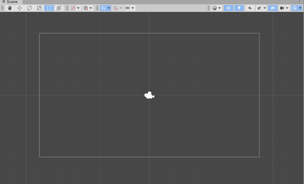
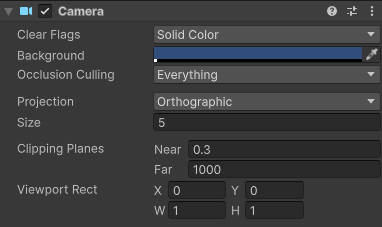
You will also notice that our scene only include a camera – by default there is no directional light, because we will be using sprite rendering in this project instead. Also, our Main Camera is a little different – our Projection is set to Orthographic, and there is no Skybox. (There can be a skybox, but none is included by default, so the Clear Flags option falls back to the Solid Color designation.
While the 2D / Orthographic camera can be used to render 3D content – remember, we did this with our Pong game – the primary method of drawing objects on the screen for 2D content is to use Sprites.
“Sprite” is a term that has been used in the video game industry almost since it’s inception. In the beginning, it referred to an image of a specific size and type that could be drawn directly to the the screen without having to be processed by the CPU, and was used to improve the performance of a game. These days, the term refers to any bitmap (or image) that is used primarily as a 2D object in a game.
For now, we will use Unity’s built-in sprites which are simple shapes that we can use to explore layers and physics.
Sorting Layers
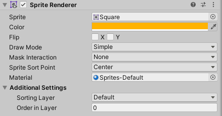
Sprite rendering works differently than 3D rendering – there are no polygons to receive and reflect light, and so the images used for sprites are simply presented (and rendered) as-is. The Sprite Renderer has different properties than the Mesh Renderer that we have previously used, including two very important ones – the Sorting Layer and the Order in Layer, and Unity’s rendering engine uses these values to determine which object to draw on top of another.
The Sorting Layer is given top priority in rendering. The higher the Sorting Layer’s index (as defined in the Tags & Layers panel that we’ve used before), the closer to the camera this layer will render, regardless of other attributes like distance (unless the sprite is behind the camera, and thus outside of the view frustrum). These are especially useful as we set up rules for our tilemaps, so that we can generate proper layers without having to worry about actual z-depths.
The next level of sorting priority when drawing is the Order in Layer setting. Overlapping objects that are contained within the same layer will use this numeric value to determine which should draw on top of the other – the higher number sprite drawing over top of the lower numbered sprite. (These numbers can also be negative, and these values can be changed programmatically if need be).
In the event that overlapping sprites do not have different layers or layer orders, then there are a few other comparisons such as distance from camera (as determined by the pivot point). But if you have overlapping sprites, it’s best to use these systems.
Part 2: 2D Physics
Unity’s 2D physics system relies on a different physics library than the 3D system, and so the sprites that we create will use a separate set of components when operating in the 2D physics world. There is a Rigidbody2D type component that performs the same task as the 3D Rigidbody, but only operates on the XY plane with the only possible rotation happening on the Z axis, towards the camera).
There are also a number of 2D Colliders which work with this system, including a BoxCollider2D, a CircleCollider2D and a CapsuleCollider2D. It is important to note that collision detection also relies upon its own method, OnCollisionEnter2D(Collision2D collision).
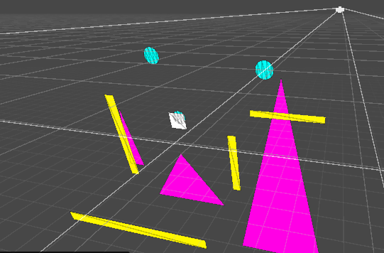
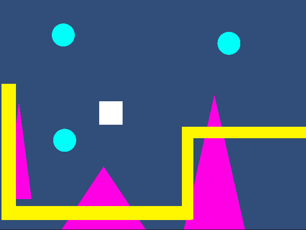
As a demo today, we built a simple environment using multiple square sprites (stretched to form rectangles), plus a few sprites with the Rigidbody controller attached. We used the Rigidbody2D.MovePosition( ) function to move our sprite towards a location that we defined as the current position + a directional offset (using the Input.GetAxis( ) for horizontal and vertical dimensions), then we replaced this with the newer Input System.
Part 3: Input System
Our projects up to this point have used Unity’s legacy system for inputs. (Here, “legacy” means “old, but we will still support it”. One day they will not longer support it at which point it becomes “deprecated”). The system was simple – we query the Input class to get the status of a keypress or axis, and read the result as a bool or float. But these days we have a wealth of options for how users might interact with our games – keyboards, mice, joysticks, gamepads, XR controllers, the list goes on.
Unity now supports a newer Input System that makes managing these device inputs simpler by allowing developers to map their controls to “actions” that can be named, and subsequently accessed in order to read their value or receive events like whether or not a button has been pressed. In today’s class we demonstrated how the default “Move” inputs could be read and implemented much in the same way we used GetInputAxis, but be interpreted regardless of controller type.
First we include our “using” statement so that the appropriate libraries are included. (Visual Studio did this automatically for us in class today.)
using UnityEngine.InputSystem;
Next, we declared an InputAction type variable.
InputAction moveAction;
Inside of our Start( ) command, we set this variable to point at the specific action we want to observe (in this case it is the “Move” value, which generates a Vector2:
moveAction = InputSystem.actions.FindAction("Move");
Now that our variable is associated, we can test the value during Update to change our direction vector. If you include the Debug statement you will notice that the vector is automatically normalized. This is the default configuration of the Input System Package settings, found under Project Settings.
void Update()
    {
        // get the movement input
        direction = moveAction.ReadValue<Vector2>();
        Debug.Log("Direction: " + direction);
    }
Part 4: Character Controller
Character Controllers are rather simple, but incredibly important. They manage the important task of moving our character through our levels based upon our input, running, jumping, and not falling through the floor. And by providing situational information such as the answer to “are we on the ground?” which is a critical question when figuring out whether or not we can “jump”.
Our Inspiration – CharacterController2D
While Unity provides a 3D Character Controller component for their games, they have yet to release their own 2D controller As such, there are a significant number of controllers that others have created and published. Today, we looked at a lovely little controller script from the Sharp Coder blog that I prefer – it’s simple, straightforward, and uses 2D Physics to handle gravity and collisions. We incorporated much of their code, with some modifications that simplify our process.
You can find their blog post and code here: Sharp Code – Unity 2D Character Controller
The first neat feature about this script is the RequireComponent instruction at the head of the file. This tells the Unity Editor that this script requires these components to be attached to the same object (in this case, Rigidbody2D and CapsuleCollider2D). If you attach this script to an object without these components, they will automatically be added.
[RequireComponent(typeof(Rigidbody2D))]
[RequireComponent(typeof(CapsuleCollider2D))]
The next feature that I appreciate about this particular controller is that they modify the rigidbody properties during the Start( ) function, to ensure that the right settings are in place. In this case, they make sure that Rigidbody2D.freezeRotation is set to true (so our character doesn’t roll over) and that the collision detection mode is set to “Continuous” rather than the default setting of “Discrete”. Continuous detection is going to be the preferred method for your player object and probably your enemy objects – you want those collisions running all the time. Finally, it set the rigidbody’s gravityScale to a value defined by this script. This is important because it will affect the speed of your vertical movement.
// preset some values
rb.freezeRotation = true;
rb.collisionDetectionMode = CollisionDetectionMode2D.Continuous;
rb.gravityScale = gravityScale;
We left out all references to camera control from the script, as we will be making our own custom camera controller later in this lesson.
Handling Inputs
The Update( ) method is used to fetch our user Inputs, which currently consist of moving horizontally, and jumping (which is a vertical motion). We modify the Rigidbody’s velocity, which is expressed as a Vector2, in order to move the controller in that direction.
Jumping can only occur when we are “grounded” (more on that in a minute) and simply replaces the velocity’s y-value with whatever we set out “jumpHeight” value to be.
Horizontal movement is a little more complicated. Sharp Coder’s features a lot of logic to determine whether how to set our “moveDirection”.
// Movement controls
        if ((Input.GetKey(KeyCode.A) || Input.GetKey(KeyCode.D)) && (isGrounded || Mathf.Abs(r2d.velocity.x) > 0.01f))
        {
            moveDirection = Input.GetKey(KeyCode.A) ? -1 : 1;
        }
        else
        {
            if (isGrounded || r2d.velocity.magnitude < 0.01f)
            {
                moveDirection = 0;
            }
        }
This version looks to see if we are pressing the A or D key, AND if we are either grounded, or already moving horizontally (by testing the absolute of the velocity’s x-value). This means that we can move while on the ground, or can adjust our movement in air if we were already moving horizontally in air. Whether or not you can control your character’s horizontal movement while in-air makes for a heated debate amongst designers. Also, what’s up with this line?
moveDirection = Input.GetKey(KeyCode.A) ? -1 : 1;
This is what is known as a “ternary operator”. It’s a conditional that works like a simplified “if” conditional. It’s structure is something = statement ? <true value> : <false value> Here, moveDirection can be set to one of two values, based on “is the A key is pressed”. If true, a value of -1 is returned, if false, 1 is returned.
The else on the original statement says if we are not pressing A or D, then our move direction should be 0. Doesn’t this sound like Input.GetAxisRaw? That’s one option that we can use for sure
// Movement controls
moveDirection = Input.GetAxisRaw("Horizontal");
But now we have the new Input System which allows us to access an action that can have multiple bindings depending on the device. How could we use this method? We set up the InputAction moveAction just like we did yesterday, then pull the x-value from the resulting Vector 2 value.
// define our action
moveAction = InputSystem.actions.FindAction("Move");

// get the move value
moveDirection = moveAction.ReadValue<Vector2>().x;
… Actually Making things Move
We used the Update( ) loop to take our settings, but for actually *moving* our object, we want to take advantage of FixedUpdate( ). FixedUpdate is called at a steady, regular interval (usually 50 times per second) and is the preferred method for working with Rigidbodies / Physics. Update is frame dependent – and that framerate will fluctuate, which is why we have to include a “deltaTime” measurement when creating motion. With FixedUpdate( ), the interval is the same every time.
Towards the end of Sharp Coder’s FixedUpdate( ) function, we see the code that sets the velocity value of our rigid body. Replacing the rigidbody with our variables this now looks like so:
// Apply movement velocity
rb.velocity = new Vector2((moveDirection) * maxSpeed, rb.velocity.y);
This method generates a new Vector2 based upon the X value of move direction, and the Y value of… whatever the Rigidbody was already doing. But… this will not work! This will return an error, because the velocity property has been discontinued in Unity 6. Instead, the Rigidbody2D library gives us access to the properties of linearVelocity (expressed as a Vector2 of world-units per second) and angularVelocity (expressed in degrees per second). Even more helpful, the class now includes direct access to both the X and Y aspects of the object’s velocity, using linearVelocityX and linearVelocityY. This means that we can simply override the X value without having to read and repeat the Y value as in the example above, and so our movement code becomes the following:
// apply the movement velocity
rb.linearVelocityX = moveDirection * speed;
Now the Y-velocity is safe to do it’s own thing, whether that is rapidly falling due to gravity, resting at zero because we are on a platform, or going positive because we are jumping.
Speaking of jumping, how can we get the value of our jump button with the new Input System? It turns out there are multiple ways. First, we can directly access keyboard keys, and evaluate their state. If we want to see if the space bar was recently released we could use any of the following formats:
Keyboard.current.spaceKey.wasReleasedThisFrame   // this looks like enumeration but is more like a property
Keyboard.current[Key.Space].wasReleasedThisFrame  // this uses an enumerated key
Notice that when accessing KeyControl directly we are testing the wasReleasedThisFrame property rather than a method. These are mapped slightly different from the Legacy input :
| Legacy Input (uses method) | New Input System – KeyControl (uses property) |
| Input.GetKey(KeyCode.Space) | Keyboard.current.spaceKey.isPressed |
| Input.GetKeyDown(KeyCode.Space) | Keyboard.current.spaceKey.wasPressedThisFrame |
| Input.GetKeyUp(KeyCode.Space) | Keyboard.current.spaceKey.wasReleasedThisFrame |
But this is just specifically querying the keyboard. The power of the Input System is that it allows us to bind actions to multiple platforms, and so there we can access this action slightly differently. First we define an InputAction variable and connect it
InputAction jumpAction;

...

void Start( )
{
    jumpAction = InputSystem.actions.FindAction("Jump");
}
And now we can access the value of that action. Note that we do this with a function rather than a property.
if (jumpAction.WasPressedThisFrame() && isGrounded)
{
    rb.velocity = new Vector2(rb.velocity.x, jumpHeight);
}
Using the action approach, we use methods to detect the states of buttons/keys:
jumpAction.isPressed();
jumpAction.WasPressedThisFrame();
jumpAction.WasReleasedThisFrame();
Part 5: Ground Detection with Physics
The beginning of SharpCoder’s FixedUpdate( ) function contains a considerable amount of logic to identify a point in space that exists inside of our player collider, and the width of the collider itself. The reason this information is important is that it will be used to create a custom collision check to see if our collider is indeed touching something. The logic goes something like this:
- Find a point just about the radius point of the lower arc on the capsule.
- Create a circle that will reach just a little lower than that arc, and check within that circle for any colliders.
- Take the list of returned colliders and check to see if one of those is NOT the player collider.
- If you find a non-player collider, you’re on the ground! If not, isGrounded remains false.
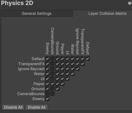
This method certainly does work, but I have a few issues with it. First, it just assumes that ANY collider that it detects is automatically the ground – but later we will use colliders with the “trigger” function that our player object will pass through, but this Physics2D.OverlapCircleAll will definitely detect. We saw before how we could use the layer matrix in Physics settings to “mask” layers from one another (like objects in Enemy layers ignoring one another). Since we only care if we hit colliders that represent the ground, why don’t we just use layers to check specifically for that?
In order to do this, I can use the third parameter of Physics2D.OverlapCircleAll( ) – a integer named layerMask. The layer mask is what is known as a “bitmask” – a way of using and manipulating the bits in a byte of information, otherwise known as a bitwise operation. These bits are set on or off, and used as a way to store information as a number. If you look at the Layer panel, you’ll notice that we only have slots in Layer 0-31, or 32 total possible values that can be set to “on” or “off”. We have a data type that is made of 32 bits – the integer. And so there is a single numeric value that represents the over 4 million possible combinations of on-off in those 32 slots. Sound complicated? It is!
Thankfully we don’t have to worry about the math for this, because Unity has already built this into our editor, with the LayerMask type. You’ve seen these variables before, in the Camera Mask settings, which determine whether a camera can view a layer or not. We declare a variable to set in the editor like so:
public LayerMask groundLayer;
This gives us a dropdown that we can use to set the layers we are interested in looking at. I’ve created a layer named “Ground”, and put all of our environment objects on that layer.
Now in FixedUpdate( ) we modify that custom physics call to include the layerMask so that it only returns colliders on the layers that we defined in the editor, which in the above image would be colliders on the “Ground” or “Enemy” layers.
Rather than go through the complicated (and frequent) calculation of the bounds and radius of the capsule collider, we are going to simply define our own. We create a Vector2 to serve as an X-Y offset from our object’s position, and a float to define the radius of the circle.
public float groundCheckRadius;
public Vector2 groundCheckOffset;
public LayerMask groundLayerMask;
Now we can use these to define our overlap circle- but how can we visualize this? Thankfully, we can draw our own gizmos in the editor. The OnDrawGizmos command can be used on objects in the editor, even when the game is not playing. Here we use the Gizmos.DrawWireSphere( ) method to draw a circle that will use the same parameters as our ground test circle, and will update its color to reflect the grounded status:
private void OnDrawGizmos()
    {
        // set ground status
        if (isGrounded){Gizmos.color = Color.green;} else {Gizmos.color = Color.red;}
        // convert the V2 into V3
        Vector3 groundCheck = groundCheckOffset;
        // draw ground circle
        Gizmos.DrawWireSphere(transform.position + groundCheck, groundCheckRadius);
    }
Next we set up the collision test with the layermask in FixedUpdate( ). Rather than sort through all of the colliders the way that SharpCoder does, I can simply check to see if there ARE any colliders returned! I set my grounded variable equal to false, then if there is length, I turn it to true.
        // reset the ground check
        isGrounded = false;

        // perform a ground check
        Vector3 groundCheck = groundCheckOffset;
        Collider2D[] colliders = Physics2D.OverlapCircleAll(transform.position + groundCheck, groundCheckRadius, groundLayerMask);

        // was there any collision within the mask layers?
        if (colliders.Length > 0) { isGrounded = true; }
Of course, if I wanted to be fancy, I could use our ternary operator to express these in one line.
isGrounded = colliders.Length > 0 ? true : false;
Tomorrow we will finish our controller by simplifying the physics check, and generating some helpful gizmos to visualize their range of effect.
Part 6: Camera Control
Now we have created a player object and let him run through our level, but very quickly the player runs out of view. There are a number of ways to address this. The simplest way to let the camera follow our player is to make the camera a child of the player object. This way, any movement of the player was automatically reflected in the camera. The end result is that the player remains perfectly still as the rest of the world moves around it.
This solution is OK, but does not really fit what we are going for. This should be a side scroller, meaning we move our camera to the side, and so we need a better solution.
Our first step is to move the camera horizontally with the player, but not vertically. We accomplish this by placing a script on the Camera object that would mirror the X value of the player object, like so:
public GameObject player;
void Update () {
    Vector3 playerposition = player.transform.position;
    Vector3 cameraposition = transform.position;
    cameraposition.x = playerposition.x
    transform.position = cameraposition;
}
IMPORTANT NOTE: Although our game is 2D, our transforms are still very much 3D. This means when working with position, we always need to use Vector3 rather than Vector2 structures.
We set a public game object and assign the Player object to it in the Inspector. Then on each frame, we find the X position and match it. The result was just OK. The side motion worked but things feel a little jittery. We want to give our player a little room to move away from the center and have the camera catch up, as though it were controlled by some camera person trying to keep up with the action. To facilitate that, we used Mathf.SmoothDamp( ), a dampening function to create a gentle curve to the updating X values, giving the camera an eased, elastic feel.
public GameObject player;
private float xVelocity = 0.0f;
// Update is called once per frame
void Update () {
    Vector3 playerposition = player.transform.position;
    Vector3 cameraposition = transform.position;

    cameraposition.x = Mathf.SmoothDamp (cameraposition.x, playerposition.x, ref xVelocity, 0.5f);
    transform.position = cameraposition;
}
SmoothDamp ( ) is part of the float math libraries, and takes 4 parameters – the start value, the end value, the current velocity (as a reference), and the time the smoothing should occur. Velocity here is tricky, as SmoothDamp ( ) will modify it each time it runs. In order to let that persist, we pass the velocity variable as a “ref”, which is the closest we will get to pointers in this class. Normally when we call a method we say “here is a value” but in this case by declaring “ref” we say “here is access to the variable itself”. SmoothDamp ( ) will update velocity each time it runs.
Playing this again, this is getting better. My player runs away and the camera catches up again. Since I’ve decided to use “Mario” rules, I want to make sure that the player can only advance, not move backwards. I’ll do that by defining two rules.
Rule #1: Any time the player moves right of the midpoint on the screen, the camera will follow.
Rule #2: The player can only move as far left as is currently visible on the screen.
Rule #1 is easy enough to implement. To do this, we set a condition around the SmoothDamp and transform position update that test to see if playerposition.x is greater than cameraposition.x and if so, it will let the camera follow.
public GameObject player;
// ref value for smoothDamp
private float xVelocity = 0.0f;
// Update is called once per frame
void Update()
{
    // match the player x position
    Vector3 playerposition = player.transform.position;
    Vector3 cameraposition = transform.position;
    if (playerposition.x > cameraposition.x) {
        // cameraposition.x = playerposition.x;
        cameraposition.x = Mathf.SmoothDamp(cameraposition.x, playerposition.x, ref xVelocity, 0.5f);
        transform.position = cameraposition;
    }
}
Rule #2 is a little trickier, as we don’t really know where the left edge is. We could do all kinds of math to figure this out, casting rays and such, but we are going to do this the lazy way.
OPTION 1: (the complicated way) In a previous semester, we included a value called “leftSideOffset” that held the distance in x units that corresponded with the left edge of the screen from the center of the camera. Since the camera is always the same z-distance from the player, this number can be a constant. In our update loop, we then check the offset as a bounding x-value for the player, with the following code:
    Vector3 checkposition = transform.position;
    float leftx = gameCamera.transform.position.x - leftSideOffset;

    if (checkposition.x < leftx) {
        checkposition.x = leftx;
        transform.position = checkposition;
    }
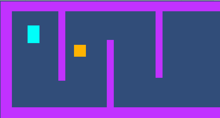
OPTION 2: (the cheap way) For this class, I have implemented a much more rudimentary system. I create an object and assign it a BoxCollider2D. I size this to span beyond the vertical length of my camera view, and move it to the very left of the camera. Finally, I make this object a child of the Main Camera, meaning that it will follow along wherever our camera goes. This prevents our player from being able to run beyond the edge of the screen. (Once we place enemy objects, you will want to adjust your Collision Matrix in the Physics 2D panel in your Project Settings, just like we did with our 3D collisions in Astral Attackers, so that your non-player objects can pass through unimpeded.)
Part 7: Sprites
“Sprite” is a term that has been used in the video game industry almost since it’s inception. In the beginning, it referred to an image of a specific size and type that could be drawn directly to the the screen without having to burden the CPU with redrawing the entire screen, and was used to improve the performance of a game. The “ghostly” nature of these objects floating over the main image inspired the developers to term them as “sprites”. These days, the term refers to any bitmap (or image) that is used and displayed primarily as a 2D object in a game, rather than as a texture or imagemap in a shader. 2D games still rely heavily on these for their characters and worlds.
Technically, our Sprite objects in Unity are still manipulated in a manner similar to mesh objects. Unity generates a simple flat shape, and applies the bitmap to it as a texture, but instead uses an optimized shader to draw this without considering many of the procedure we would include in 3D rendering. Even our text objects generate a simplified mesh and apply the font as a texture to it. For our purposes, however, we will refer to “mesh” objects as those belonging in the 3D realm, and our “sprite” object meshes simply as Sprites.
A “sprite sheet” refers to an image that contains a collection of images to be used as sprites. Sometimes these are collections of common objects or “tiles” that can be used to create a level, as we will do here, but more often you will encounter them as collections of sequential frames for animation. The reason that these sprite sheets are used is that it is far more costly to load a number of small images into memory and swap them in and out as objects in the scene than it is to have a single large image and instead adjust which coordinates of the image will be drawn in a particular frame.
For this demo, we are going to use three files as sprites:

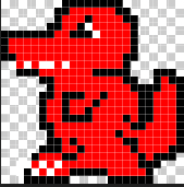
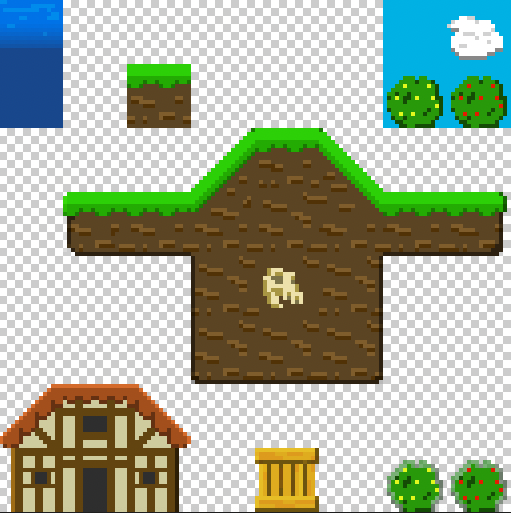
In this case, we have:
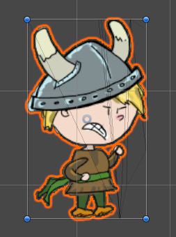
- Our hero, a little Viking Boy (a high resolution drawing, and part of a larger sprite sheet comprised of frames of animation. I’ll be showing these next week)
- An enemy (a very small pixelated dragon, also from a sprite sheet comprised of frames of animation)
- Environment Tiles (a 128×128 sprite sheet composed of 16×16 pixelated blocks, each one intended as a “Tile” for our Tilemap)
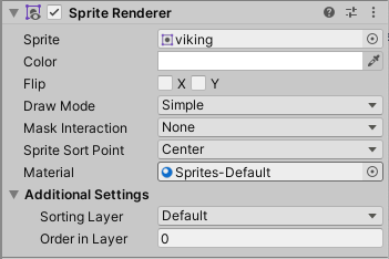
We start by placing an instance of our Viking Boy into the Scene. You’ll notice when we do this, that we have a new Component, the Sprite Renderer. (This replaces the Mesh Renderer and Mesh components from our 3D games.) You will also notice that the default tool to move the Sprite is the Rect Tool, located to the right of the Scale button. (The hotkey for this is: Y) You can still use move/scale/rotate, but the Rect tool is easier for 2D workflows.
Importing and Editing Sprite Sheets
Sprites and sprite sheets come into our game the same way as the rest of our resources – we import them using Assets> Import New Assets…
Once imported, you will want to select it so that you can make edits to the Import Settings. Remember, these assets are external to your editor. Nothing you do here will change the contents of the sprite sheet, only how the Editor interprets it. Also remember that once you have made changes you will need to confirm the changes by clicking the Apply button at the bottom of the panel.
If you started your project with Unity’s 2D template, then your image’s Texture Type should automatically be set to “Sprite (2D and UI”. This tells Unity a bit about how you intend to use the file. (If it is not, go ahead and make that change.)
If your sprite is a single image, then the default Sprite Mode setting of “Single” will work for you. However, if this is a sprite sheet, change this setting to “Multiple”, which lets Unity know to expect more than one object will come out of this texture atlas. Your Pixels Per Unit setting serves as the scale for how big your sprites should be if you drop them into the scene (of course you can always scale them to meet your preference). By default this value is 100 pixels to a unit. This is great for our Viking Boy as this will make him about 2 units high, but our Environment object is only using 16×16 pixels per sprite. We change this value to “16” so that each block will be 1 unit by 1 unit.
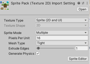
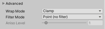
Next, we want to correct the “fuzzy” look of our smaller objects. If we post this to our level, we see the edges are blurry. This is because Unity is “sampling” the image to visualize it at a higher resolution. This is great for things like photorealistic textures, but terrible for our pixel art. To correct this, we go to the Advanced Settings and set the Filter Mode to “Point (no filter)”. This setting controls how to handle scaling images. Using “point” tells the editor that we want the images sharp edges to be preserved.
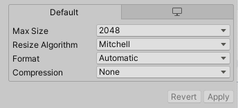
If you are using pixel art, and are still getting images that don’t look quite right (i.e. the edges are sharp, but the sprites themselves are blocky or the colors somehow.. wrong) you might be having issues with the “compression” settings. Unity automatically puts compression on all images that it imports, but for pixel art this can often create a degraded look, and the gains are super minimal because the source images are so small to begin with. To correct this, look at the Default settings at the bottom of Import Settings and set your Compression to “None”. This will remove any adjustment and use your source material as-is.
Now it is time to split the sprites, which we will do with the Sprite Editor, which you access from the sprite’s Import Settings.
NOTE: If you want to use the Sprite Editor with the 3D template, you may need to install the 2D Sprite package, which you can do from the Package Manager. If you are starting from a 2D template, this package is already activated.
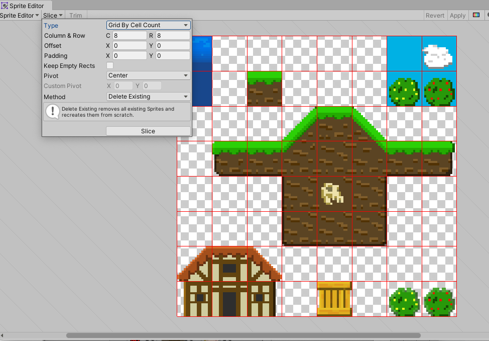
For our Environment sprite sheet, go to the Slice dropdown button at the top and select Grid by Cell Count. This will let you define the how the image should be split into pieces. For this object, we want to set the count to 8 columns and 8 rows. Keep the pivot at “Center” (you’ll want this for proper placement in the Tilemap.) Once you are ready, hit slice. You will see that small boxes have been drawn for these, but also that any empty square has been removed. If you update your sprite sheet with more sprites, you may need to run the Sprite Editor again to include the new content.
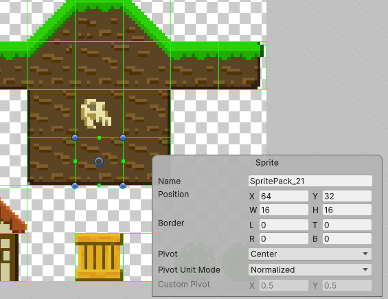
If you click one of these boxes, you will get a Rect controller, and call up information about the sprite itself. You can adjust values, or change the name of the individual sprite.
When you have completed your set-up & edits, click the “Apply” button in the Sprite Editor window, and then also the “Apply” button in the Import Settings. Now in the Asset window your sprite sheet will have a small arrow in a circle next to it. Clicking on this arrow will expand the list to show the individual sprites contained within this object.
Part 8: Tilemaps
Now that we have set up our sprites, it is time to build a level. While we could place individual sprites and colliders throughout the environment, Unity gives us an excellent tool for designing sprite content – the Tilemap. The Tilemap is a system of components which handles Tile assets and allows you to place them in your scene.
To create a new Tilemap, go to Create > 2D Object > Tilemap. This will also generate a Grid object, and your Tilemap will be a child of this object. (You can create more than one Tilemap, each will become a child of this Grid). This parent object has a Grid component within which you can set the size, spacing, and orientation of the Grid.

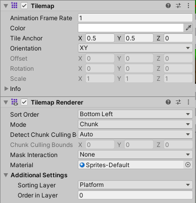
The Tilemap object will contain the Tilemap Component and the Tilemap Renderer component. The most important setting to notice here is the Sorting Layer setting in the Tilemap Renderer. For our game, we will set up multiple Tilemaps under the same grid, and set them to different sorting layers to create foreground and background objects.
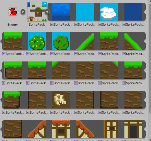
Once your Tilemap is created, you will want to create a Tile Palette – a collection of tiled sprites that you can use to populate the grid cells on your Tilemap. Access this by going to Window > 2D > Tile Palette. Once here, select “Create New Palette…” and give it a location and a name. Then you can drag sprites into this window which will create Tiles for each sprite. (You will see a window asking where you want to save these in your Asset directory. I recommend creating a new folder, as these can get pretty numerous if you are working with even a modestly sized sprite sheet.)
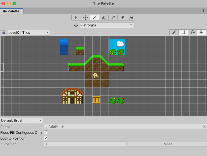
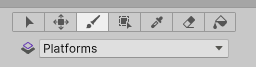
The Tile Palette window features a list of tools at the top. These are:
- Select – allows you to select one or more grid cells
- Move – allows you to relocate a tile (you must first select the tile)
- Paint – select a palette tile or tiles and use this to paint that selection onto your scene’s tilemap.
- Box Fill – fill an area of your tilemap with the selected tile(s) from your palette
- Pick – click on a tile to change your active brush selection to that type of tile
- Erase – click on a tile to remove it
- Flood Fill – fill a large area with the active tile(s)
Below the tile tools is the Active Tilemap setting. If you have multiple tilemaps (which is common with layering) you will want to make sure that you have the correct Tilemap selected before you paint. For this reason, it is recommended to give each of your Tilemaps a unique name that identifies their purpose (such as Foreground, Background, etc)
Rule #2 is a little trickier, as we don’t really know where the left edge is. We could do all kinds of math to figure this out, casting rays and such, but we are going to do this the lazy way.
Tilemap Collider
Now that we’ve created our level, we need to set up colliders. We could painstakingly create and hand-place dozens of box colliders, or we could simply select our Platform tilemap and apply the Tilemap Collider. This will use the physics shape generated for each sprite (based on it’s alpha channels) to generate colliders around each tile. We set our Platform Grid object to the “Ground” layer, and just like that our character is running on platforms!
The Pixel Perfect Camera
As we are using non-filtered sprites (16×16 pixel tiles with the “point” filter on), it is possible that our camera may not render all of the intersections of tiles as seamless, uninterrupted pixels. Instead, we may find that we have some tearing (more commonly found as vertical stripes). This is caused by a sampling error where “most” of the pixels should not be drawn, and so it leaves this blank. (this problem tends to be more pronounced when using pixel art with the point filter – larger images have less likelihood of this sampling error)
One way that designers will address this is by creating textures that are designed to have a one-pixel overlap from one another. This means that one will always overlap the other, so no seam will be present. This version requires meticulous planning, and careful slicing of your sprites in the editor.
The other method to cover this is to use the Pixel Perfect Camera, which will resize your camera to a compatible depth to ensure that such tearing does not happen. It is great at cleaning up this problem, but it will resize your screen so make sure that you preview this.
2D Pixel Perfect: How to set up your Unity project for retro 8-bit games – [ Unity Blog ]
Part 9: Enemy Movement & Triggers
Finally, let’s create some enemy objects to interact with. We will get them into our scene, behaving the way we expect them to behave (patrolling platforms!) and show a simple processing for player or enemy death.
We added a Circle Collider 2D, and Rigidbody2D component to it, and created a simplified version of our character controller script to automate its movement. We use a simple boolean in our script called “faceLeft” which will indicate if our enemy is facing left or right, used that value to determine the direction (represented by -1 : 1). We then used the SpriteRenderer component to set the flipX value (which flips the horizontal orientation of the sprite itself)
To create behaviors, we will use Triggers to give our Enemy the illusion of intelligently patrolling its platform. Triggers are a variation of colliders that don’t actually collide – they simply define a volume, and that volume will create a collison-like event when another object’s collider enters it.
For our purposes, we are going to create a “turn around” box – a cube volume that our enemy will enter, register, and react by reversing direction. First, create an empty object, add a Box Collider 2D, and check the Is Trigger box. Create a tag called “TurnAround” and assign it to this box. Make this object a prefab so that we can place them throughout the level. Then we add this to the Enemy script:
private void OnTriggerEnter2D(Collider2D collision)
{
    if (collision.gameObject.tag == "TurnAround")
    {
        faceLeft = !faceLeft;
    }

}
Once the Enemy object enters the trigger object, it checks for the “TurnAround” tag, and if it finds one, it will invert the “faceLeft” value of the Enemy causing him to walk in the other direction. This will only fire when the enemy first enters the volume as OnTriggerEnter2D only occurs at the first point of overlap. You can use OnTriggerExit2D to register when the overlap has ended, or OnTriggerStay2D to confirm that an overlap is ongoing.
NOTE: Trigger’s use the OnTrigger commands, as opposed to the OnCollision commands. Unity treats these differently, so they will only apply to the corresponding setting for isTrigger. Also, because this is 2D physics, note the 2D designation at the end of each of these. OnCollisionEnter and OnCollisionEnter2D use different physics sys
CharacterController2D.cs
using UnityEngine;
using UnityEngine.InputSystem;

// CharacterController2D is based upon the 2DCharacterController from Sharp Coder Blog
// URL: https://www.sharpcoderblog.com/blog/2d-platformer-character-controller
//
// Adapted by Tom Corbett on 10/20/25

[RequireComponent(typeof(Rigidbody2D))]
[RequireComponent(typeof(CapsuleCollider2D))]

public class CharacterController2DScript : MonoBehaviour
{
    // Move the player in 2D space
    public float speed = 1f;
    public float jumpHeight = 2f;
    public float gravityScale = 1f;

    // private values
    private Rigidbody2D rb;

    private InputAction moveAction, jumpAction;
    private float moveDirection = 0f;

    // Ground Detection
    [HeaderAttribute("Ground Detection")]
    public bool isGrounded = false;
    public float groundCheckRadius;
    public Vector2 groundCheckOffset;
    public LayerMask groundLayerMask;

    void Start()
    {
        // get the components
        rb = GetComponent<Rigidbody2D>();

        // configure the Rigidbody
        rb.freezeRotation = true;
        rb.collisionDetectionMode = CollisionDetectionMode2D.Continuous;
        rb.gravityScale = gravityScale;

        // define our actions
        moveAction = InputSystem.actions.FindAction("Move");
        jumpAction = InputSystem.actions.FindAction("Jump");
    }

    void Update()
    {
        // set the move direction
        moveDirection = moveAction.ReadValue<Vector2>().x;

        // get the jump action
        if (jumpAction.WasPressedThisFrame() && isGrounded)
        {
            rb.linearVelocityY = jumpHeight;
        }
    }

    void FixedUpdate()
    {
        // reset the ground check
        isGrounded = false;

        // perform a ground check
        Vector3 groundCheck = groundCheckOffset;
        Collider2D[] colliders = Physics2D.OverlapCircleAll(transform.position + groundCheck, groundCheckRadius, groundLayerMask);

        // was there any collision within the mask layers?
        if (colliders.Length > 0) { isGrounded = true; }

        // apply the movement velocity
        rb.linearVelocityX = moveDirection * speed;
    }

    private void OnDrawGizmos()
    {
        // set ground status
        if (isGrounded){Gizmos.color = Color.green;} else {Gizmos.color = Color.red;}
        Vector3 groundCheck = groundCheckOffset;
        // draw ground circle
        Gizmos.DrawWireSphere(transform.position + groundCheck, groundCheckRadius);
    }
}
EnemyScript.cs
using UnityEngine;

public class EnemyScript : MonoBehaviour
{
    public float enemySpeed;
    private Rigidbody2D rb;
    private SpriteRenderer sprite;
    public bool facingLeft = true;

    void Start()
    {
        rb = GetComponent<Rigidbody2D>();
        sprite = GetComponent<SpriteRenderer>();
    }

    void Update()
    {
        // if the values match, reverse the values
        if (facingLeft == sprite.flipX) { sprite.flipX = !facingLeft; }
    }

    private void FixedUpdate()
    {
        // set the x-velocity to positive or negative speed, depending on which way we are facing.
        rb.linearVelocityX = facingLeft ? -enemySpeed : enemySpeed;
    }

    void OnTriggerEnter2D(Collider2D collision)
    {
        if (collision.gameObject.tag == "TurnAround")
        {
            facingLeft = !facingLeft;
        }
    }

    void OnCollisionEnter2D(Collision2D collision)
    {
        if (collision.gameObject.name == "Player")
        {
            Destroy(collision.gameObject); // kill the player
        }
    }
}
CameraScript.cs
using UnityEngine;

public class CameraScript : MonoBehaviour
{
    public Transform player;
    public float smoothTime = 1f;
    public float currentVelocity = 0f;

    void FixedUpdate()
    {
        Vector3 cameraPosition = transform.position;
        // cameraPosition.x = player.position.x;
        if (player.position.x > cameraPosition.x)
        {
            cameraPosition.x = Mathf.SmoothDamp(cameraPosition.x, player.position.x, ref currentVelocity, smoothTime);
        } else
        {
            currentVelocity = 0;
        }
        transform.position = cameraPosition;
    }
}